PowDeR/RF Power Devices: Difference between revisions
No edit summary |
No edit summary |
||
| Line 18: | Line 18: | ||
All the amplifiers have a separate supply line (+12V nominal), and PA has two: one to bias the gates of the active devices inside and one for the drains. All the amplifiers have to be powered up and down in a correct sequence to ensure that no damage is inflicted to the system under any operating condition. Also, the temperature of the PA is never to exceed 55°C, so a temperature measurement circuit was considered to be mandatory. | All the amplifiers have a separate supply line (+12V nominal), and PA has two: one to bias the gates of the active devices inside and one for the drains. All the amplifiers have to be powered up and down in a correct sequence to ensure that no damage is inflicted to the system under any operating condition. Also, the temperature of the PA is never to exceed 55°C, so a temperature measurement circuit was considered to be mandatory. | ||
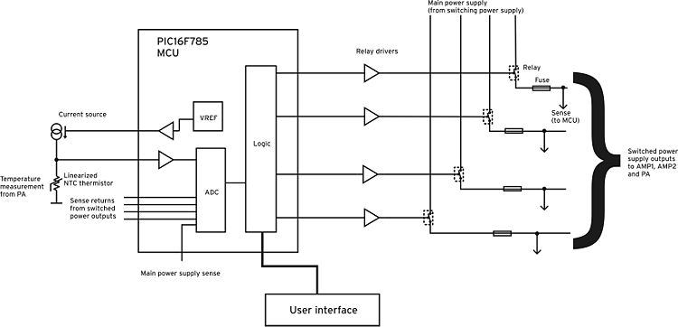
For such purposes a control unit has been custom developed based on a microcontroller. The block diagram of the control unit is sketched in Fig. 2. | For such purposes a control unit has been custom developed based on a microcontroller. The block diagram of the control unit is sketched in Fig. 2. | ||
[[File:cu_en.jpg| | [[File:cu_en.jpg|750px|thumb|left|Fig.2. Block diagram of the amplifier CTL unit.]] | ||
Revision as of 13:06, 24 June 2010
10 GHz RF Power Amplifier for Continuous Wave Load Pull measurements
Introduction
We developed a custom rackmount amplifier capable of delivering a RF continuous power of 8W on a 50W load at a nominal frequency of 10GHz. The amplifier has been integrated into an existing on-wafer 2GHz CW RF Load Pull measurement system, thus extending its performace capabilities to the frequency of 10GHz , and is based on commercial amplifier modules, all manufactured by Kuhne Electronic GmbH, Germany, [1].
System description
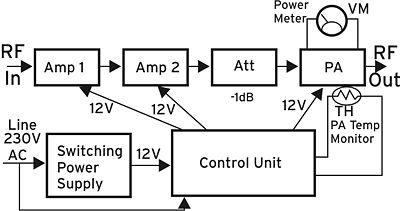
The system consists of a cascade of three amplifier modules, Amp1, Amp2 and PA, as shown in Fig.1.
The signal to be amplified (RF In) is used to feed the pre-amplification chain Amp1 – Amp2. These amplifiers (Kuhne P/N: MKU PA 102AL) are characterized by a nominal gain of 18.5dB and maximum saturated power 300mW. The output of Amp2 is fed into PA through a 2W 1dB attenuator, Att (Aeroflex Inmet P/N: 18AH-01, USA). The purpose of such attenuator is to prevent the signal at the input of the power amplifier PA from exceeding 300mW under any working condition, which is the absolute maximum power that can be fed into PA. The power amplifier PA (Kuhne P/N: MKU PA 102XL) is designed to work at the nominal frequency of 10GHz and is capable of yielding a maximum saturated power of 12W and a nominal gain of 20.7dB. The signal chain from RF In to RF Out is thus characterized by a typical RF gain of 56.7dB. The power amplifier PA has an auxiliary output providing a voltage proportional to the output power. Such voltage has been used to feed a power meter VM based on a LED bargraph. All the amplifiers have a separate supply line (+12V nominal), and PA has two: one to bias the gates of the active devices inside and one for the drains. All the amplifiers have to be powered up and down in a correct sequence to ensure that no damage is inflicted to the system under any operating condition. Also, the temperature of the PA is never to exceed 55°C, so a temperature measurement circuit was considered to be mandatory. For such purposes a control unit has been custom developed based on a microcontroller. The block diagram of the control unit is sketched in Fig. 2.

