Research Activity: Difference between revisions
| Line 138: | Line 138: | ||
in this spectral region is a major challenge due to the high conductivity losses of metals and high absorption of dielectrics. Numerical results show the possibility to reach propagation loss two decades lower than the bulk absorption losses of the material used to fabricate the fibre, over a wide range of wavelength. The purity of the aperture field distribution at the | in this spectral region is a major challenge due to the high conductivity losses of metals and high absorption of dielectrics. Numerical results show the possibility to reach propagation loss two decades lower than the bulk absorption losses of the material used to fabricate the fibre, over a wide range of wavelength. The purity of the aperture field distribution at the | ||
HC-PBGF section suggests a possible employment of such a structure as aperture antenna, for possible feed systems in THz applications. | HC-PBGF section suggests a possible employment of such a structure as aperture antenna, for possible feed systems in THz applications. | ||
[[File:fibre.png|700px]] | |||
Fig.15 Possible photonic band gap fibres cross sections, investigated at THz. | Fig.15 Possible photonic band gap fibres cross sections, investigated at THz. | ||
Revision as of 22:19, 12 July 2009
TOPICS
The Alessia Polemi research activity begins at the Department of Information Engineering of the University of Siena, in the period of preparation of the master thesis degree, oriented to the asymptotic study of the Green’s function associated with truncated periodic arrays of elementary sources embedded in multilayered environment. This activity continued after the master thesis degree in cooperation with Prof. Felsen from the University of Boston, and it produced the publication of a sequence of three papers on this subject. Contemporarily, the scientific activity of Alessia Polemi also investigated the field of electromagnetic analytical and numerical methods, particularly referring to the high frequency techniques for the prediction of the electromagnetic scattering, with Prof. Roberto Tiberio and Prof. Stefano Maci as supervisors. The research activity has also been developed in the framework of national research programs (PRIN), university research programs (PAR), and in the framework of projects financed by the Italian Space Agency (ASI). She also participates to European research programs, as ACE and EAML. The experience on periodic structures and on Green's function for multilayered structures allowed her to start a fruitful collaboration with Politecnico di Torino, to assest new and efficient tools for the analysis of aperiodic and periodic printed elements embedded in dielectric materials. The collaboration with Politecnico di Torino has been also addressed to the problem of kernel regularization in 3D singular integral equations.
Recently, her reasearch activity is focusing on lens antenna, for which she is involved in a European Research Networking Program (RNP) with University of Rennes, on RFID antenna design, on microwave radiometers, and on metamaterials and plasmonic structure at optical frequencies, on which she is undertaking an international collaboration with Prof. Nader Engheta (University of Pennsylvania) and Prof. Andrea Alù (University of Austin, Texas).
ASYMPTOTIC METHODS FOR ARRAY ANTENNAS
The research activity in this area has the objective the development and application of asymptotic methods for analysis and design of array antennas embedded in multilayered dielectric environment. In particular, the research is mainly dedicated to the characterization of diffraction phenomena, generated by the periodicity truncation (semi-infinite array, sectoral array) through the array Green’s function (AGF), and through the subsequent integration of the representation into full-wave codes for the efficient analysis of printed antennas.
Array Green’s function (AGF): diffraction phenomena generated by edge truncation on dielectric slab
For a correct description of the diffraction generated by the array edge truncation, and interpreted in terms of rays according to the Geometrical Theory of Diffraction (GTD) genaralized to periodic structures, the AGF must take into account not only for the presence of dielectrics, but also for the presence of periodicity. If the array is infinite, the Floquet theorem allows to express the AGF as superposition of a complete set of modes (Floquet modes), weighted by the spectral Green’s function of the single element in the periodicity. If the array is finite, this expansion cannot be directly applied. The aim of this research branch is that to formulate an AGF for an efficient treatment of truncated periodic array on dielectric slabs. The goal is reached referring to appropriate canonical problems. The first is that of introducing the truncation effects due to the edge (semi-infinite array), either for an array of line sources [R2], or for an array of point sources [R1][R4][C1]-[C5]. The integral describing the diffraction from the array edge can be evaluated applying asymptotic techniques. The knowledge of the asymptotic array Green’s function, not only is of advantage for the computational times, but it also allows to check separately the various field contributions (truncated Floquet modes, truncated surface and leaky waves), predicting the eventual interaction [R5][R6][C9][C11].

Fig.1 Phenomenology associated with Semi-Infinite Array Green’s Function (AGF).(left) Semi-infinite elementary sources on multilayered environment (middle) Topology of the AGF (right) Schematic representation of the transition from a conical wave to a plane surface wave in 3D and 2D views
Array Green’s function (AGF): diffraction phenomena generated by vertex truncation on dielectric slab
In order to complete the extension o the Geometrical Theory of Diffraction (GTD) generalized to periodic structures it is necessary to develop an efficient asymptotic solution for the canonical problem associated with a sectoral array, where the truncation is present along both directions, including either spatial diffraction contribution or guided waves diffraction contribution. An hybrid technique based on an appropriate decomposition into canonical problems is developed to include diffraction terms, with particular care to the observation on the array surface, which is of basic importance when the continuity conditions of electric and magnetic fields must be applied [C14][C20][C23]. The method is based on an iterative process of subtraction, from the infinite array, of canonical problems constituted by semi-infinite and sectoral arrays. Each of these problems can be treated separately, applying convenient techniques, according to the observation region [C26][C28][C33].

Fig.2 Phenomenology associated with the Sectoral Array Green’s Function (AGF).(left) Sector of elementary sources on multilayered environment (middle) and (right) Schematic representation of the transition from edge and vertex diffracted waves.
Introduction of the array Green’s function inside full-wave codes for the analysis of larege array antennas
The asymptotic Green’s function allows also to describe the field contributions due to the presence of double truncations. Thus, it could be efficiently employed to extend the applicability of full-wave methods also to very large array. This objective is reached solving the MoM through an appropriate regularized integral equation (“fringe” equation), where the unknown current is expanded on entire domain basis function, with behaviour imposed by dominant diffraction contributions [C6][C7][C10][C12][C16]. The main objective of this activity is concerned with an efficient evaluation of the Array Green’s Function (AGF) and its clever application into a MoM, while remaining in the application framework of arrays or periodic surfaces which exhibit weak variability with respect to periodicity of geometry and excitation. The high frequency method used here has the advantage to be additive with respect to the one associated with the infinite structure, with additional (edge) contribution which is not invariant by phase shifted translation, thus allowing the reuse of already existing numerical codes [C20]. The strategy adopted is briefly the following. All the elements of the array are discretized with triangular cells, where the Rao-Wilton-Glisson (RWG) basis functions are defined; in the AGF-MoM approach, the MoM problem is set-up and solved for each element in isolation, instead to implement the global array MoM reactions with a reduction of complexity and memory occupation. Thus, the key advantage in using the AGF in the MoM is in the possibility of evaluating and solving only the MoM matrix of each element against itself, instead of the MoM matrix of the whole array. The integration of the AGF with the MoM is organized in two steps and repeated for all the array elements.
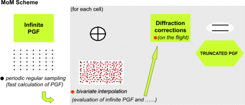
Fig.3 MoM Strategy for finite size arrays
GREEN'S FUNCTION CHARACTERIZATION FOR STRATIFIED DIELECTRICS
The activity is essentially devoted to the modelling of printed antenna.
Characterization of guided phenomena
The presence of dielectric substrates influences the real radiating antenna performance and complicates the electromagnetic analysis. In fact, the structure supports guided waves propagation, in particular surface waves or leaky waves. On one hand, these kinds of guided waves can degrade the radiating antenna performance, on the other hand they can be employed to improve directivity/gain. Infact, composite planar dielectric structures used for increasing the directivity of a point
source, have been investigated since many years. This substrate/superstrate structure was demonstrated to establish a resonance condition, which maximizes antenna gain, radiation resistance, and radiation efficiency. Particular attention has been given to the physical interpretation of this resonance gain effect, which can be described in terms
of leaky waves (LW) excited in the structure. Under certain resonance conditions, a pair of weakly attenuated TE/TM leaky waves become the dominant contributions to the antenna aperture field. Although the demonstrated interest in such
type of configurations, the polarization characteristics of the structure wasn't investigated enough. The aim of this reasearch activity has been to rigourously demonstrate that the conventional choice of the stratification, not only ensures a large aperture field, but the same field is also well polarized when excited by any linearly polarized point
source [R7] [C29].

Fig.4 (left) Topological investigation of coalescence of leaky waves (resonance condition) in a substrate/superstrate structure; (middle) and (left) purity of polarization of the copolar component of a linear polarized source embedded in such a substrate/superstrate structure.
Asymptotic models
To characterize the dielectric structures, different methods have been employed for the efficient evaluation of the Green’s function, which, if known analytically in the spectral domain (wavenumber), can be transformed into the spatial domain through the Fourier transformation. In the hypothesis of high frequency, the evaluation of this integral can be performed asymptotically, through dominant contribution of the integral (saddle point and poles residues contributions). The Green’s function expressed in terms of these contributions, even if approximated, is convenient in terms of calculation time [R7].
Numerical models
In the case when the radiating element is embedded into multilayered dielectric structures, the Green’s function calculation even in the spectral domain is more complex, and the integral relevant to the Fourier transformation is typically solved numerically. Nevertheless, this integral shows some difficulties related to the presence of poles associated with surface and leaky waves, and to its oscillating behaviour. In this context, more effort has been devoted to the choice of alternative integrations paths and integration techniques which can improve the efficiency of numerical codes [RT1]. To accelerate the Green’s function calculation even in the near zone where the asymptotic technique fail, the research activity has regarded the implementation of numerical codes based on approximations known in literature as complex images , which allow the representation of the Green’s function in terms of a few spherical sources, whose ray can be complex. Particular attention has been given to improve the convergence of these methods, with the scope to be inserted into a MoM code for the analysis of printed antennas, already developed in co-operation with Politecnico of Turin, and up to now based standard integration techniques [RT4][RT5]. The convergence has been improved by properly extracting dominant contributions of the Green’s function, related to the quasi-static term, and to the guided waves. This approach is particularly efficient in the near zone, where other techniques, as the asymptotic one, fail.
HIGH FREQUENCY METHODS FOR SCATTERING PREDICTION FROM PERFECTLY AND NON PERFECTLY CONDUCTING OBJECTS
This reasearch activity concerns the development of new uniform diffraction coefficients and incremental techniques, suitable for prediction of scattering from perfectly and non perfectly conducting obstacles. This activity is of fundamental importance in the analysis of the field scattered or diffracted by large objects in terms of wavelength, such for the design and analysis of large antennas (e.g., reflectors), for the prediction of Radar Cross Section propagation in complex environments (e.g., urban propagation), for antenna installation and inter-antenna coupling (e.g., on ships, aircrafts, space platforms…).

Fig.5 Different scenarios for applications of high frquency methods
Generalization of Incremental Theory of Diffraction
Within this research activity, a general systematic procedure has been reached for defining incremental field contributions in the framework of scattering prediction from large conducting objects [R3]. The procedure is based on a generalization of the Incremental Theory of Diffraction (ITD) localization process for uniform cylindrical, local canonical problems with elementary source illumination and arbitrary observation aspects. In particular, it is shown that the spectral integral formulation of the exact solution for the local canonical problem may also be represented as a spatial integral convolution along the longitudinal coordinates of the cylindrical configuration. Its integrand is then directly used to define the relevant incremental field contribution. For the sake of convenience, but without loss of generality, this procedure is illustrated for the case of local wedge configurations. Also, a specific suitable asymptotic analysis is developed to derive new closed form high-frequency expressions from the spectral integral formulation. These expressions for the incremental field contributions explicitly satisfy reciprocity and are applicable at any incidence and observation aspect. This generalization of the ITD localization process together with its more accurate asymptotic analysis provides a definite improvement of the method
.
Extension of Geometrical Theory of Diffraction for analysis of scattering from canonical planar structures
In the framework of high frequency techniques, the reasearch activity has been addressed to the extension of methods for scattering prediction from planar structures such as wedge, also non perfectly conducting (dielectric, if necessary), with reference to the canoncal problem associated with the half-plane and the junction of two parts plane [C24]. In the contest of the Uniform Theory of Diffraction (UTD), usually applied to the scattering of metallic or opaque surfaces, a heuristic formulation, simple but sufficiently accurate for most engineering applications, can be derived starting from the rigorous formulation of non penetrable screens, involving standard reflection and transmission coefficients, easily calculated for planar dielectric structures. These coefficients contain already known transition functions [C18][C21][C22]. Particular attention has been given to the inclusion of surface waves that can be guided by non perfectly cinducting surfaces [C25][C27][C32]. The analysis, UTD-based, has been developed by calculating surface waves poles associated with the non perfectly conducting wedge faces (half-plane or two-parts junction), and from them appropriate diffraction coefficients are derived, heuristically extrapolated from the relavant canonical problems of surface impedance wedges
.

Fig.6 (left) High frequency localization principles; (right) Overall compensation mechanism in scattering from a dielectric half plane
Extension of Incremental Theory of Diffraction for analysis of scattering from planar canonical structures
The applicability of the Incremental Theory of Diffraction (ITD), tipically limited to the scattering from metallic surfaces, has been extended to non perfectly conducting surfaces (alse dielectric). The ITD is based on a suitable use of canonical problem solutions which locally approximate the structure geometry. A localization process allows to define incremental coefficients which, integrated along discontinuity lines or shadow lines, furnish the diffracted field[R3]. The main objective has been the derivation of a heuristc ITD formulation, simple but still accurate for most of engineering applications, starting from the rigorous formulation for metallic screens, with reference to the canonical problem associated with half-plane and two-parts junction [C13][C17][C18][C21][C30]. The so derived incremental diffraction coefficient is implicetely reciprocal and reduces to the ITD coefficient for conducting faces wedges (pec or pmc), in limiting cases. Through this formulation has been treated the scattering from faceted structures formed by composite materials, also in caustic zones, where the UTD ray-description becomes singular. In addiction, the ITD diffraction coefficient has also been written in terms of "fringe" contribution, in order to be inserted in already available PO codes.
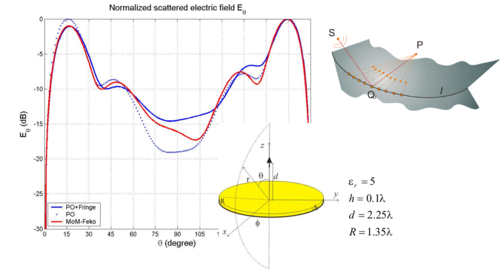
Fig.7 ITD application to circular dielectric structures
Extension of Incremental Theory of Diffraction to complex source illuminations
When representing arbitrarily shaped antenna radiation patterns, Gaussian Beams (GBs) turn out as very effective. GBs are solution of Maxwell equations only in the paraxial region but they are deeply concerned with the concept of the Complex Source Point (CSP), whose field is Maxwellian throughout the space (also outside the paraxial region), as can be easily inferred
via an analytic continuation of the source point Green’s function when the source position is allowed to be complex. Such a GBs/CSPs representation can be used within a ray code to predict the interaction between antenna and the actual environment, if standard diffraction formulations are extended to the CSP case. The CSP extension of ray techniques like UTD appears to be substantially more problematic than that of incremental ray theories, such as ITD. Thus, this activity has been oriented to analyze this CSP extension of discrete and incremental ray techniques, with particular reference to the ITD formulation [R9][C11][C14].
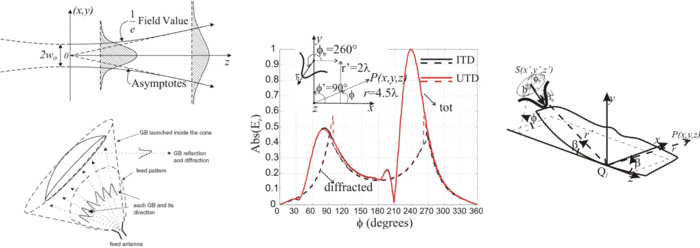
Fig.8 ITD extension to Complex Source Points (CSP)
DESIGN OF ANTENNAS FOR MODERN WIRELESS APPLICATIONS
Recently, the activity has been oriented towards emerging radianting systems employed in different wireless applications(RFID,Bluetooth, ZigBee, body-centric networks, sensors networks, etc.). In this field, the activity concerns the analysis, design and prototyping of printed technology antennas, which are versatile, easy to be realized, and at low cost.

Fig.9 Emerging wireless applications
Antennas for sensors networks
In sensors networks, antennas are mounted on-board and disseminated in different areas (environment, on human body, cars, etc.). They usually communicate with a main access point, which can be a personal computer, a PDA, or other. Antennas for these kinds of applications must be omnidirectional, in order to guarantee communication independently on their actual displacement with respect to the main access point. Unfortunately, their placement on objects of different nature degrades the performance, such as the efficiency and the input impedance. Especially this last must be taken under control in order to guarantee the right matching with the sensor itself. As a consequence, the antenna design must include the presence of possible objects thus resulting in customized design. A particular application has been developed in the framework of a Research Contract involving the company MicroDetectors spa (Modena, Italy) and the Institute of Applied Acoustic (CNR-IDAC, Rome, Italy). This work concerned the design of an antenna part of a radio sensor unit (for temperature applications) based on the employment of a surface acoustic wave (SAW) device. The matching between the SAW and the antenna on the Tag is a critical issue of the design, if no matching network are used in order to maintain the costs low. The antenna efficiency must be taken under control, and in particular its gain pattern, to guarantee omnidirectionality and to improve the radio activation distance. Possible shieldings have also been investivagetd to allow the sensor to be independent on its placement [C24].

Fig.10 (left) Geometry of the proposed antenna; (middle) gain pattern; (right) experimental measure set-up
Antennas for RFID tags
Radio Frequency Identification (RFID) is a recent technology which found applications in many practical areas such as automatic identification and location of objects, people tracking, supply chain management, security access to controlled areas, etc. A typical component of an RFID system is a small tag or transponder, which is located on the objects to be identified. A passive tag is composed by a transponder chip (IC) and a matched antenna enabling it to either capturing electromagnetic energy from an interrogating field or communicating with an RFID reader or interrogator. Passive RFID at UHF band (866-869 MHz, European band) and Microwave (2.45 GHz) communicate using the modulated scattered technique, where the reflected signal from the tag is modulated by the IC connected directly to the antenna. To obtain the maximum power transfer to the chip, a tag antenna is typically designed to be conjugate matched to it. In order to reduce costs and size, matching networks or other lumped elements are avoided. Moreover, the microchip is usually presenting a highly capacitive input impedance, thus the antenna input impedance should be intrinsically inductive. As a consequences, the design of tag antennas, that can be effectively integrated with the IC transponders, is one of the major constraint. This activity mainly concerns the development of a planar dual band slot-type binocular tag antenna operating at the frequencies of 868MHz and 2.45GHz is presented. The particular geometry resulting from the design has suggested the name of binocular antenna. This shape allows to obtain a good conjugate match to the input impedance of a chip operating at both frequency bands. The proposed antenna is also mechanically robust against possible vibrations and provide a quasi isotropic radiation patterns [C22].

Fig.11 (left) Geometry of the proposed antenna; (right) current displacement at the two operating frequencies
Microwave radiometer
Within a Nation Research Program (PRIN), a low-cost integrated X-band microwave radiometer for ground-based applications has been designed. The microwave frequencies offer advantages over the well established InfraRed (IR) technology, because a microwave signal can penetrate all materials (except of metals) allowing detection also through thick smokes and vapors. On the other hand, the longer wavelength of the microwave radiation, compared to IR, reduces the spatial resolution. An usual way to improve the spatial resolution is to address higher frequencies (up to the extreme limit of imaging capabilities) to get a better antenna directivity even if at the cost of a more expensive electronics of the microwave front-end. This research activity has regarded the design and prototyping of the antenna, designed as an array of patches, where number of elements, spacings and feeding currents have been optimized to fulfill requirements of low side lobe level and good crosspolarization. First the single radiator has been optimized, then the feeding network and the overall array displacement have been designed [R8][C17]. The antenna, printed on a standard single layer Taconic substrate, has been then prototyped and its performance, in terms of input impedance and radiation pattern, measured with a customized set-up [C23].
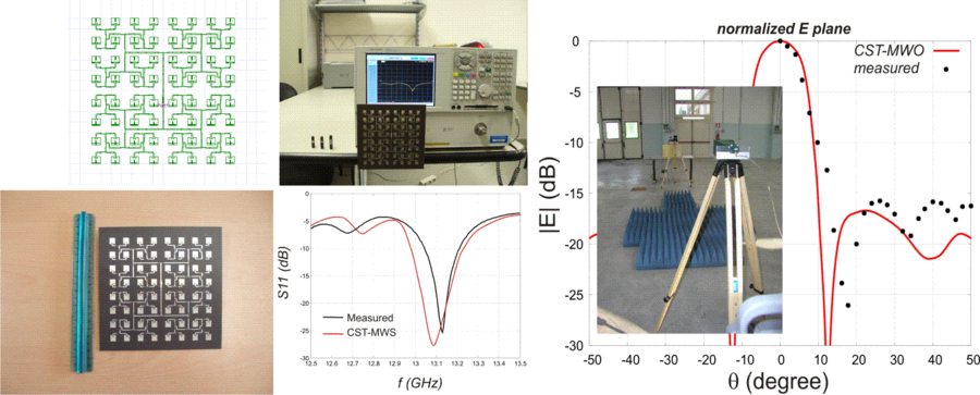
Fig.12 (left) Geometry of the array antenna and prototype; (middle) input impedance charcterization; (right) radiation pattern charcterization
REGULARIZATION OF 3D SINGULAR KERNEL IN INTEGRAL EQUATIONS
The problem addressed in this research activity with Politecnico di Torino regards the well known problems that the Green’s functions employed in integral equation methods, such as the Method-of-Moments (MoM), diverge when observation and source points coincide; this is at the origin of the difficulties in computing the MoM matrix entries, and in handling the near-field interactions in FFT-based fast methods and other sampling-based methods. We have shown [R10][C16][C18][C19] that this singularity can be avoided, and a modified regular Green’s function can be used instead. This latter is obtained from the spectral representation of the usual Green’s function via windowing of its spectrum; the width of the spectral window depends on the size of the mesh employed for discretizing the problem, so that the proposed regular Green’s function is a mesh-adapted regular kernel. Numerical results for 3D antenna and scattering problems discretized with Rao-Wilton-Glisson (RWG) functions, have been produced to show the effectiveness of the approach, both for uniform and non-uniform meshing. They show that the proposed method yields accurate solutions also for the antenna input impedance

Fig.13 (left) Basis and test functions lying in different planes, generically oriented; (right) amplitude of the Fourier Transform of an RWG function of the mesh for both radial and angular component
ONGOING ACTIVITIES
Ridge Bandgap Waveguides
Hollow Core Fibre for THz Applications
Hollow Core Photonic Band Gap Fibres (HCPBGFs) are investigated in order to obtain low loss waveguiding and good aperture field distribution in the terahertz region (0.1 − 10THz) of the electromagnetic spectrum. Waveguides and antennas design in this spectral region is a major challenge due to the high conductivity losses of metals and high absorption of dielectrics. Numerical results show the possibility to reach propagation loss two decades lower than the bulk absorption losses of the material used to fabricate the fibre, over a wide range of wavelength. The purity of the aperture field distribution at the HC-PBGF section suggests a possible employment of such a structure as aperture antenna, for possible feed systems in THz applications.
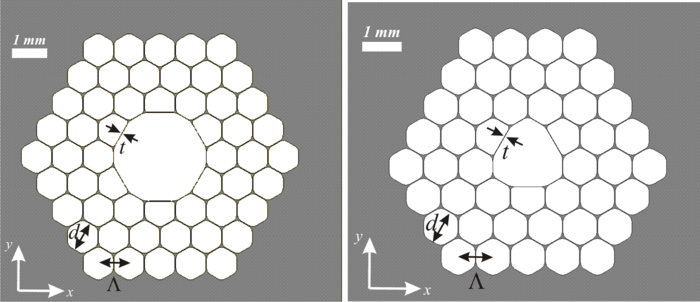 Fig.15 Possible photonic band gap fibres cross sections, investigated at THz.
Groove Waveguides at Optical Frequencies
PUBLICATIONS